As electric vehicles become increasingly popular around the world, communication between electric vehicles and charging stations has become essential for managing and controlling the charging process.
In this context, EVCC, or Electric Vehicle Communication Controller, plays an important role. It helps electric vehicles and charging stations exchange charging requirements, charging status, and other key information.
1. Charging Standards
Electric vehicles generally support two charging methods: AC charging and DC charging.
Since the battery is a DC power source, the final energy supplied to the battery must be DC. During AC charging, the onboard charger, or OBC, converts AC power into DC power. During DC charging, the charging station completes the AC-to-DC conversion before supplying power to the vehicle.
Different countries and regions use different charging interfaces and communication protocols for AC and DC charging.
Although charging standards vary across countries, the charging connector must include high-voltage pins for energy transmission, such as L and N for AC charging, and DC+ and DC- for DC charging.
In addition to high-voltage pins, the charging connector also includes low-voltage signal pins. These pins are used to exchange information between the charging station and the vehicle.
For example, during AC charging, the voltage is usually fixed. The onboard charger needs to know the maximum output current of the charging station to avoid overload or damage. This current limit information must be exchanged between the charging station and the vehicle.
During DC charging, both charging voltage and charging current change dynamically. Different vehicle battery packs have different voltage platforms, and different charging stages require different current levels. Therefore, charging voltage and charging current information must be exchanged between the charging station and the vehicle.
For EVCC, its main role is to handle signal communication between the charging station and the vehicle. It does not directly connect to high-voltage power lines.
Therefore, from the EVCC perspective, the main difference between charging standards is not the high-voltage pins, but the way low-voltage communication signals are transmitted.
Taking Chinese GB/T standards and European/U.S. standards as an example:
For AC charging, both GB/T and European/U.S. standards can use the CP pin for signal transmission. The charging station outputs a 1 kHz PWM signal on the CP pin. The vehicle reads the duty cycle of the PWM signal to determine the maximum output current of the charging station.
For DC charging, GB/T uses CAN communication. The charging station and vehicle exchange charging voltage, charging current, battery capacity, vehicle status, charging station status, and other information through CAN messages.
GB/T 27930 is customized based on the J1939 protocol over CAN bus.
European and U.S. DC charging standards use PLC communication. PLC signals are modulated onto the CP pin PWM signal. Therefore, the CP pin can transmit both PWM signals and PLC frames.
PLC frames are organized in a similar way to Ethernet frames. The difference lies in the physical layer signal levels, which are handled by a dedicated PLC chip. From a software perspective, the PLC communication interface can be treated similarly to an Ethernet interface.
PLC-based communication protocols, such as ISO 15118 in Europe and DIN 70121 in the U.S. and European CCS systems, are based on TCP/IP, similar to other Ethernet application-layer protocols such as HTTP, MQTT, and SOME/IP.
The main difference between European and North American charging standards is the connector shape. Europe uses CCS2, while North America uses CCS1. However, the communication method is basically the same.
In summary, apart from connector shape, the major difference between charging standards lies in how charging voltage, charging current, and charging status information are exchanged during charging.
Especially in DC charging, Chinese GB/T and European/U.S. standards use two completely different communication methods: CAN and PLC. This is why charging stations and electric vehicles from different regions cannot directly match each other, and why Chinese domestic EVs cannot directly charge on European or U.S. charging infrastructure without protocol adaptation.
2. Charging Communication Solution for Export Vehicles
To solve the problem that Chinese domestic EVs cannot directly use European or U.S. charging stations, the hardware solution usually includes the following modifications:
The original GB/T charging socket on the electric vehicle is replaced with a European or U.S. standard charging socket.
An EVCC is added to the vehicle.
The low-voltage signal pins in the charging socket, such as PP, CP, and PE, are connected to the EVCC.
The AC high-voltage pins, such as L and N, are connected to the onboard charger, or OBC.
The DC high-voltage pins, such as DC+ and DC-, are connected to the high-voltage bus or battery through the high-voltage distribution unit or high-voltage relay.
The EVCC uses two CAN channels to communicate with the BMS and OBC.
3. AC Charging Software Solution
For AC charging, the EVCC usually detects the connection between the vehicle and the charging station through the PP signal.
It reads the PWM signal on the CP pin to obtain the charging station status, maximum output current, and other information.
The EVCC then sends this information to the OBC through CAN bus based on a customized private protocol.
After receiving CAN messages, the OBC understands the charging station’s output capability and converts AC power into DC power.
At the same time, the OBC communicates with the BMS through another CAN channel to complete battery charging.
4. DC Charging Software Solutions
There are two main software solutions for DC charging.
Solution 1: No Modification to BMS Software
During DC charging, the EVCC communicates with the charging station through PLC frames over the CP pin, based on ISO 15118 and DIN 70121.
At the same time, the EVCC communicates with the BMS through CAN based on the GB/T 27930 protocol.
The EVCC forwards charging voltage, charging current, and other information between the charging station and the BMS.
It also controls the BMS to start or stop insulation detection and to open or close the high-voltage relay.
Solution 2: BMS CAN Protocol Modification
During DC charging, the EVCC communicates with the charging station through PLC frames over the CP pin, based on ISO 15118 and DIN 70121.
At the same time, the EVCC communicates with the BMS through a customized private CAN protocol.
The EVCC forwards charging voltage, charging current, and other key charging data between the charging station and the BMS.
5. System Architecture
The system architecture for enabling Chinese domestic EVs to charge on European and U.S. charging stations includes the charging socket, EVCC, OBC, BMS, VCU, and PDU.
Charging Socket Pin Functions
DC+ / DC-
High-voltage DC power pins.
L1 / L2 / L3 / N
High-voltage AC power pins. L1, L2, and L3 are live wires, while N is the neutral wire.
PE
Low-voltage ground.
PP
Charging connector insertion detection signal. The resistance between PP and PE changes according to whether the charging connector is inserted.
CP
Used to transmit both PWM signals and PLC communication messages.
6. Module Definitions
OBC — Onboard Charger
Converts AC power into DC power.
BMS — Battery Management System
Collects battery status, controls charging voltage and charging current, and calculates the battery SOC.
VCU — Vehicle Control Unit
Communicates with the EVCC and controls the BMS. In some system architectures, the EVCC can communicate directly with the BMS, and a VCU may not be required.
PDU — Power Distribution Unit
A high-voltage distribution box or high-voltage relay. It can be understood as a high-voltage switch controlled by the BMS.
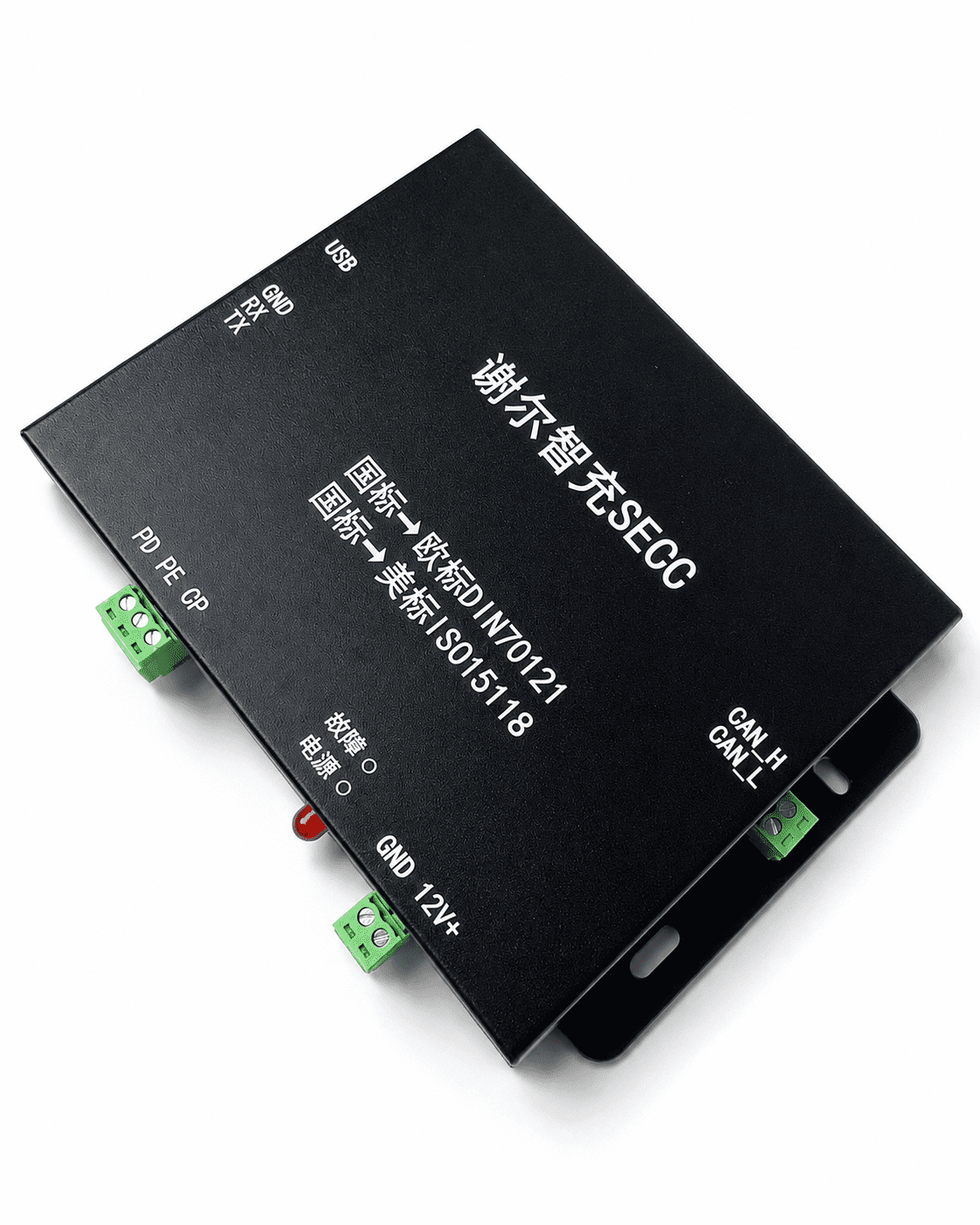
7. EVCC Wiring Description
The charging socket includes temperature sensors and an electronic lock.
Therefore, in addition to the wires connected to the charging station, the socket also includes three temperature sensor wires, two wires for electronic lock control, and two wires for electronic lock position detection.
The main components connected to the EVCC include the charging socket, BMS, and OBC.
The pin functions connected to the EVCC are as follows:
PE
Low-voltage ground, connected to EVCC GND.
PP
Charging connector insertion detection signal. The EVCC detects the connector insertion status by measuring the resistance change between PP and PE through an analog input channel.
CP
Used to transmit both PWM signals and PLC messages. The CP signal is connected to the EVCC. Inside the EVCC, it is connected to PLC communication, analog signal acquisition, and PWM acquisition circuits to realize communication, PWM voltage measurement, frequency measurement, and duty cycle measurement.
PTC0 / PTC1 / PTC2
Temperature sensors connected to EVCC analog input channels. They are used to monitor the temperature of the charging socket and prevent overheating during charging.
Electronic Lock Control
Connected to the EVCC H-bridge control pins to control the locking and unlocking of the electronic lock.
Electronic Lock Position
Connected to the EVCC analog input channel. The EVCC determines the lock status by measuring resistance changes.
A+ / A-
Simulate the low-voltage auxiliary output of a GB/T charging station. They are generally used to wake up the BMS.
CC2
Simulates the CC2 pin of a GB/T charging station. After the charging connector is inserted, it outputs a CC2 signal so that the GB/T BMS recognizes the connection as a GB/T charging station.
CAN_1
Communicates with the BMS through GB/T 27930 or a customized private protocol.
CAN_2
Communicates with the OBC through a customized private CAN protocol.
8. Product Features
The EVCC product has the following features:
It is compatible with AC and DC charging stations in different regions, including European, U.S., and Japanese standards.
It supports ISO 15118, DIN 70121, and GB/T 27930 protocol standards, as well as charging protocol conversion.
It supports customized CAN protocols.
It can simulate GB/T charging station signals such as CC2, A+, and A-.
It supports temperature sensors and electronic locks for different charging sockets.
It supports CP edge wake-up.
It uses a multi-CAN design to support different vehicle electronic and electrical architectures.
It provides multiple high-side outputs, which can be used to wake up the BMS or control LEDs.
It supports UDS, or Unified Diagnostic Services, in compliance with ISO 14229 and ISO 15765.
It supports hardware customization and can be integrated into other controllers such as VCU and BMS.
It supports software updates through the CAN interface, making maintenance and upgrades easier.
It supports secure transmission protocols such as TLS, as well as PnC, or Plug and Charge.
It supports ISO 15118-20, enabling smart charging and bidirectional power transfer.
It supports VAS services based on ISO 15118, as well as protocols such as HTTPS and VDV 261.
9. Application Scenarios
EVCC is mainly used for new energy vehicles and energy storage devices exported to Europe, North America, Japan, and other overseas markets.
Typical application scenarios include:
Road Vehicles
Passenger cars, light trucks, heavy-duty trucks, buses, RVs, dump trucks, and other vehicles used on public roads.
Special Vehicles
Mining trucks, sanitation vehicles, low-speed logistics vehicles, electric forklifts, AGVs, electric tricycles, and other working vehicles used in closed or dedicated environments.
Electric Motorcycles
Electric two-wheelers that require fast charging.
Energy Storage Devices
Mobile energy storage systems and commercial or industrial energy storage devices.