I. Basic Definition: Roles of SECC / EVCC
1. SECC
SECC stands for Supply Equipment Communication Controller, the communication controller installed inside DC fast charging piles and serving as the core communication unit of charging equipment:
- Interfaces with power modules, contactors, insulation detection circuits, emergency stop circuits and OCPP cloud back-end platforms;
- Completes full-process digital interaction with vehicle-mounted EVCC for charging;
- Executes power scheduling, safety protection, session management and Plug & Charge authentication.
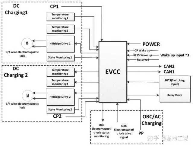
2. EVCC
EVCC is short for Electric Vehicle Communication Controller. It is bound with the vehicle BMS, responsible for reporting battery status and issuing charging demand instructions.
Two Main Standard SECC Communication Stacks
- CCS DC (European Standard, ISO 15118-2/3): Communication between SECC and EVCC via PLC (Power Line Communication) over the CP line, supporting Plug & Charge (PnC);
- GB/T DC (Chinese National Standard, GB/T 27930): SECC communicates with EVCC through CAN bus without PLC.
II. Physical Hardware Communication Link (Mainstream CCS European Standard DC Pile)
5 core signal wires of the charging gun realize layered communication:
- CP Control Pilot with dual functions:
- Low-frequency PWM (1kHz): Physical handshaking; 5% duty cycle triggers digital communication between SECC and EVCC;
- High-frequency PLC carrier signals superimposed on CP line: High-speed bidirectional digital data transmission between SECC and EVCC.
- PP Proximity Pilot: Identifies rated cable current and gun lock status via resistance;
- DC+/DC-: High-power DC energy circuit;
- PE Protective Earth: PLC signal return path and safety grounding.
Physical Layer Communication Principle (PLC Carrier)
The SECC integrates a PLC modulation & demodulation chip, which modulates ISO 15118 messages into high-frequency carrier waves and superimposes them on the 1kHz PWM CP line. The vehicle-side EVCC demodulates and restores digital messages, enabling high-speed bidirectional data transmission via only a single CP wire without extra communication cables.
III. SECC Full Protocol Layer (CCS DC per ISO 15118)
Four layers from top to bottom, with SECC handling forwarding, verification and control for each layer:
- Application Layer: V2G Message Layer (Core Business of SECC)
EXI-compressed XML messages define all charging commands (session management, authentication, power negotiation, pre-charging, charging stop and settlement). - Transport Layer: TCP/DTLS Secure Encryption
SECC and EVCC establish a TCP channel with bidirectional TLS certificate authentication to prevent message tampering and counterfeit vehicles/charging piles. - Network Layer: SLAC Automatic IP Assignment
SECC acts as a LAN gateway, dynamically assigning IP addresses to EVCC via SLAC protocol to build a vehicle-pile local area network. - Physical Link Layer: PLC Power Line Carrier
Modulation & demodulation on CP line, underlying data transceiving, CRC check and error retransmission for fault tolerance.
IV. Full Communication Timing Sequence Between SECC and DC Charging Pile (CCS DC Fast Charging)
Phase 1: Physical Gun Insert Wake-up & PWM Handshake
- Gun insertion changes PP resistance → SECC confirms cable connection and closes electronic gun lock;
- SECC outputs 1kHz PWM signal with 5% duty cycle (trigger condition for DC fast charging digital communication);
- EVCC detects 5% duty cycle, wakes up BMS and initializes PLC carrier communication.
Phase 2: PLC Network Establishment (SLAC)
SECC activates SLAC protocol to broadcast and assign IP addresses; EVCC acquires LAN IP to complete underlying link connection.
Phase 3: Bidirectional TLS Security Authentication (Core SECC Authentication Function)
- EVCC initiates TLS handshake and exchanges digital certificates of both parties;
- SECC verifies vehicle certificate chain for Plug & Charge (PnC) and matches the cloud owner account;
- An encrypted communication session is established; all subsequent charging messages are transmitted in ciphertext to prevent unauthorized charging.
Phase 4: Charging Session Initialization
EVCC sends SessionSetupReq → SECC allocates a unique session ID to create the current charging session.
Phase 5: Power Parameter Negotiation (Core SECC Power Scheduling Function)
- EVCC transmits
ChargeParameterDiscoveryReq: reporting battery maximum voltage, maximum charging current, SOC, temperature and charging curve; - SECC reads hardware capabilities of the charging pile (maximum module power, grid current limit, insulation status);
- SECC calculates the safe charging range comprehensively and responds with
ChargeParameterDiscoveryResto agree the maximum voltage and current for this charging session.
Phase 6: Cable Check & Insulation Detection (SECC Safety Control)
- EVCC sends
CableCheckReqto request SECC to inspect cables, gun lock and insulation performance; - SECC controls IMD (Insulation Monitoring Device) to perform high-voltage insulation detection on DC busbar;
- If insulation test passes, confirmation message is returned; charging process terminates immediately and alarm is triggered upon insulation fault.
Phase 7: Pre-charging (Avoid Impact Damage to Contactors)
- EVCC issues
PreChargeReqwith current battery voltage value; - SECC controls power modules to slowly raise output voltage to approach battery voltage;
- When voltage difference meets threshold, SECC closes primary DC contactors on the pile side; EVCC closes on-board battery contactors to complete high-voltage circuit connection.
Phase 8: Closed-loop Dynamic Charging (Real-time Power Control by SECC)
Core closed-loop communication mechanism with millisecond-level periodic interaction for dynamic power regulation:
- EVCC sends
CurrentDemandReqevery 50~250ms to dynamically request target charging current (automatic switch between constant current and constant voltage charging); - SECC executes three-fold safety verification:
- Not exceeding rated power of the charging pile;
- Not exceeding allowable grid output power;
- No abnormal pile temperature, module temperature or busbar insulation;
- SECC replies with
CurrentDemandResand synchronously adjusts output voltage & current of DC power modules; - Bidirectional status reporting:
- EVCC transmits BSM battery messages: cell voltage, cell temperature and SOC;
- SECC reports pile operating status: output power, module temperature, contactor status and accumulated energy.
Phase 9: Charging Termination Process (Triggered by Either Party)
Trigger conditions: Full SOC, gun unplug, over-temperature, insulation fault, emergency stop activation
- EVCC sends power-off request
PowerDeliveryReq; - Upon receiving the instruction, SECC controls power modules to reduce output current to zero;
- SECC and EVCC open DC contactors sequentially;
- SECC discharges residual high voltage on busbar;
- Charging session closes; SECC uploads charging energy, cost and duration to OCPP cloud platform.
V. Differences in SECC Communication under Chinese National Standard GB/T 27930 (Domestic DC Piles)
- Physical Link: No PLC; SECC communicates directly with EVCC via CAN bus;
- No TLS certificate or Plug & Charge function; messages are transmitted in plaintext CAN frames;
- Fixed-cycle message interaction:
- BMS (EVCC): BRM battery parameters, BCL real-time current demand, BSM battery status;
- SECC (Charger): CRM pile power capability, CCS real-time pile output status;
- Pre-charging, insulation detection and power-off logic are consistent with CCS standard; only message IDs and data formats differ.
VI. Coordination Principle Between SECC and Other Modules of DC Charging Pile
- SECC ↔ DC Power Module: Communication via RS485/CAN bus, transmitting target voltage/current commands and reading module temperature & fault codes;
- SECC ↔ IMD Insulation Monitoring Device: Real-time reading of high-voltage insulation resistance; charging terminates immediately if resistance falls below safety threshold;
- SECC ↔ Contactor Driver: Controls closing/opening of high/low-voltage contactors and on/off of pre-charging loop;
- SECC ↔ OCPP Cloud Backend: SECC acts as gateway to upload charging data and receive remote start/stop, price adjustment and firmware upgrade commands;
- SECC ↔ HMI Touch Screen: Synchronously displays SOC, charging power, charging cost and fault codes.
VII. Summary of Core Communication Principles
- Underlying Transmission: European standard relies on PLC carrier over CP line for single-wire digital communication; Chinese national standard adopts CAN bus;
- Central Control Unit: SECC serves as the unique coordination hub of charging piles, integrating communication, power regulation, safety control and cloud interconnection;
- Closed-loop Control: EVCC submits current demand → SECC performs safety verification → DC output is adjusted dynamically with millisecond closed-loop control to ensure safe fast charging;
- Safety System: Triple protection consisting of hardware insulation detection, software TLS encryption and periodic status monitoring; SECC cuts off high voltage and terminates communication immediately once any fault occurs.
Supplementary Glossary
- SECC: Supply Equipment Communication Controller
- EVCC: Electric Vehicle Communication Controller
- BMS: Battery Management System
- PLC: Power Line Communication
- CP: Control Pilot
- PP: Proximity Pilot
- IMD: Insulation Monitoring Device
- OCPP: Open Charge Point Protocol
- PnC: Plug & Charge
- SLAC: Service Location Protocol Auto-Configuration
- TLS: Transport Layer Security
- DTLS: Datagram Transport Layer Security
- EXI: Efficient XML Interchange
- V2G: Vehicle-to-Grid